Loop Wiring Diagram Instrumentation
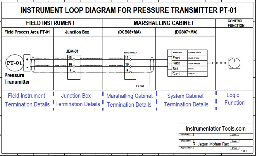
A plot plan shows the exact location of each equipment. Due to lack of marshalling strip, enhanced spi loop diagram typically only shows the device panels instrument and coic terminations using electronic marshalling conclusion cioc is configurable for:

Basics of The 4 20mA Current Loop Learning Instrumentation And Control Engineering
Hereof, what is a p&id loop?.
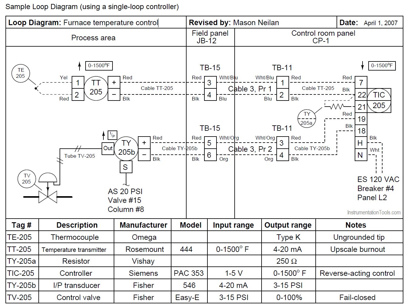
Loop wiring diagram instrumentation. This diagram illustrates wiring for one switch to control 2 or more lights. As a minimum, an instrument loop diagram shall contain the information covered below. The instrument loop diagram is a composite representation of instrument loop information.
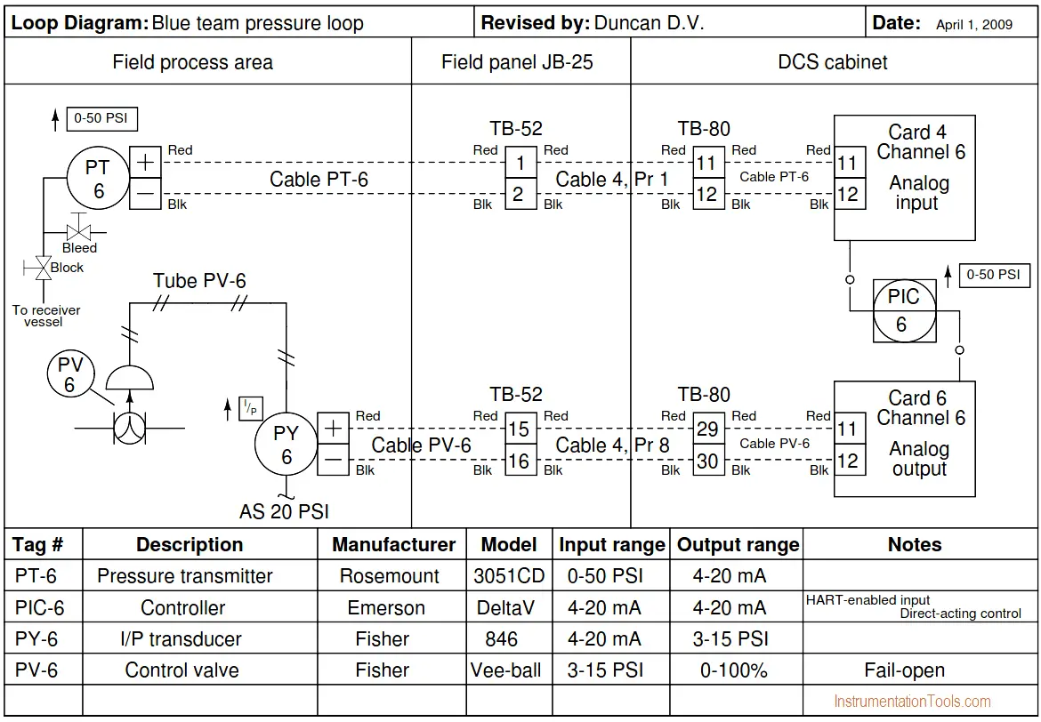
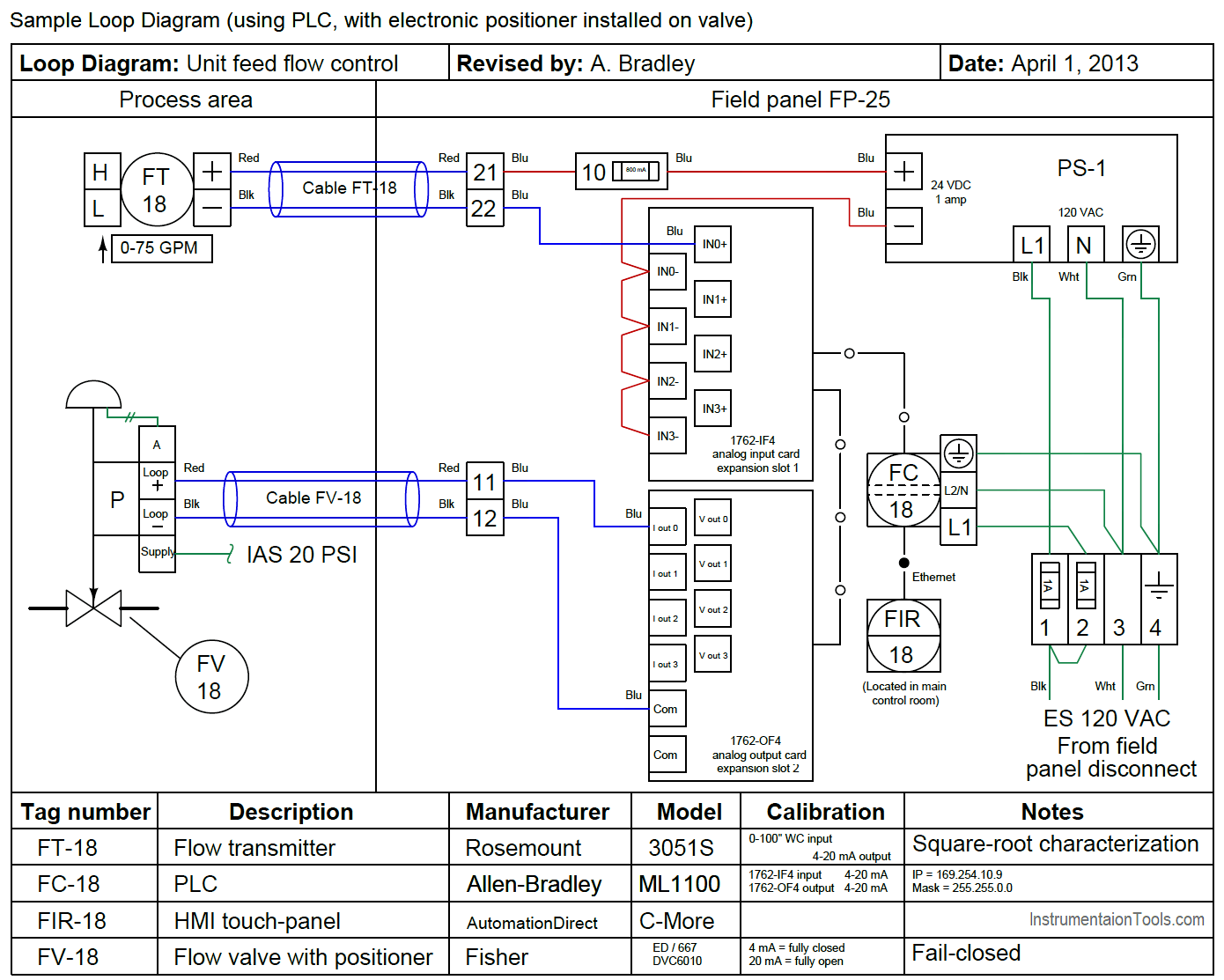
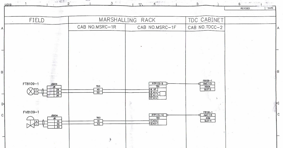
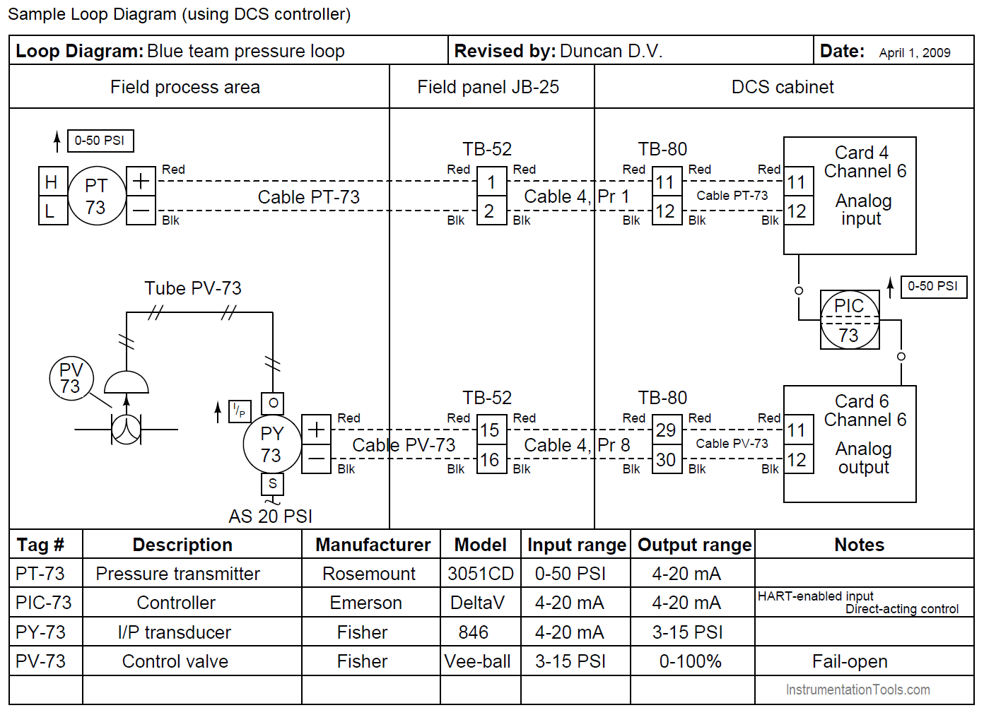
Each instrument bubble in a loop diagram represent an individual device with its own terminals for connecting wires. The process is illustrated in. Loop diagram symbols and p&ids p&ids and loop diagrams p&ids and loop diagrams are construction and documentation drawings that depict the flow of the process and illustrate the instrumentation.
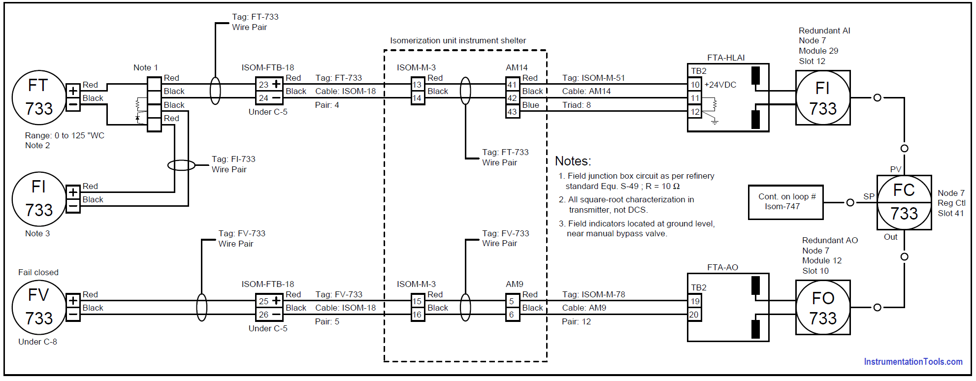
Instrument loop diagram that information is spread among many other documents and is not readily available. Mainly for construction contractor who will install and wire all the loops. Each instrument bubble in a loop diagram represent an individual device with its own terminals for connecting wires.
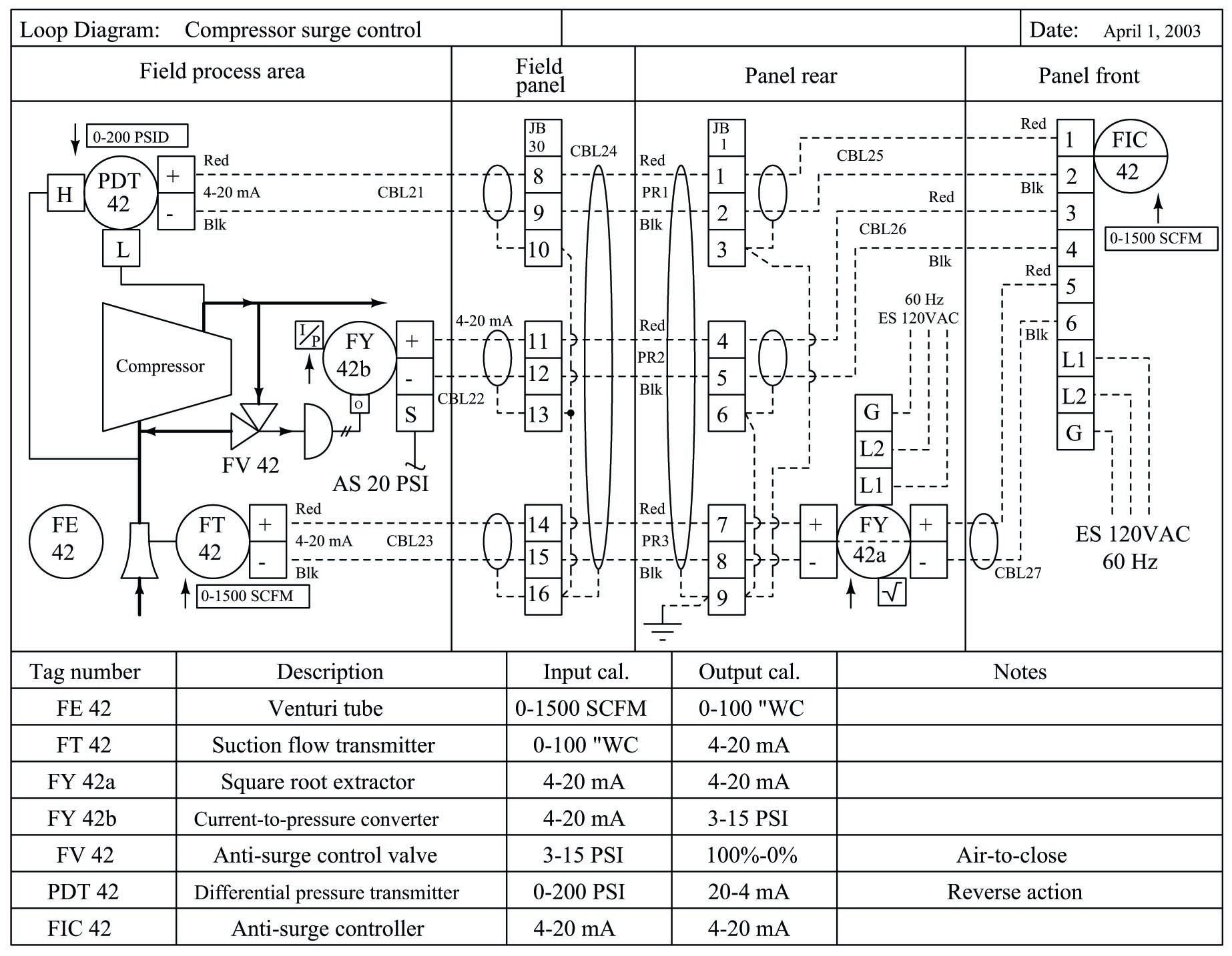
Instrument loop diagrams are also called instrument loop drawings or loop sheets. It contains all associated electrical and piping connections and should contain all of the information needed to accommodate the intended uses. C from cable reel to cable tray the cable is fed from the top of the reel to main tain required curvature.
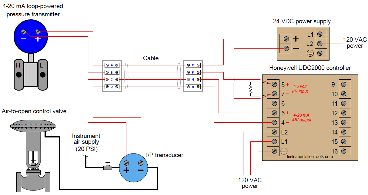
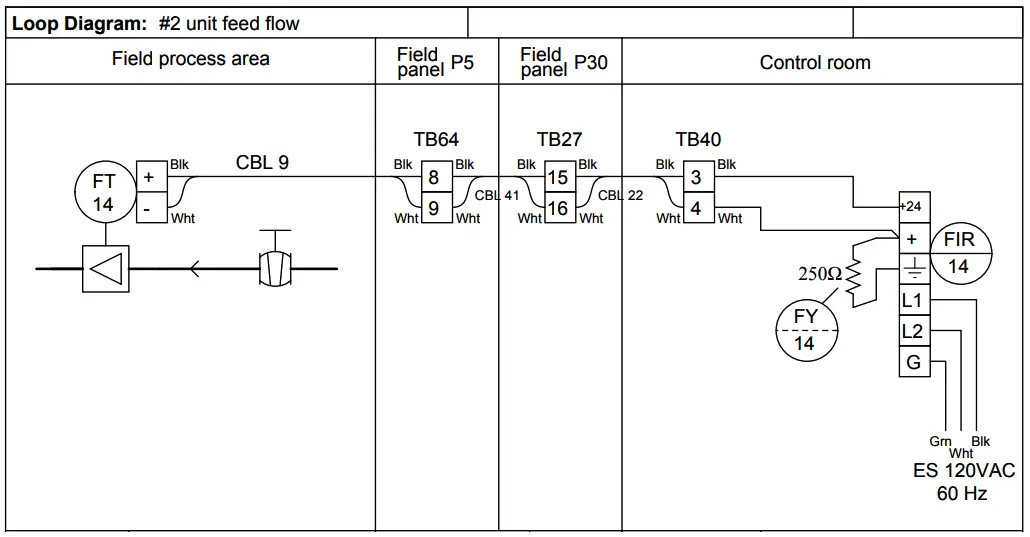
It helps them to track each and every tag correctly and easily while keeping log of the activities. Loop diagrams are very important instrumentation design deliverable. A transmitter analog output loop contains the transmitter, power supply, and the receiving device which could be a plc or dcs.
Loop diagrams are imagined and understood by many people as a kind of extended wiring diagrams. Dashed lines in instrument drawings represent individual copper wires rather than whole cables. Dashed lines in instrument drawings represent individual copper wires rather than whole cables.
The actual wiring connection between the transmitter and the power supply depends upon which type. Each instrument bubble in a loop diagram represent an individual device with its own terminals for connecting wires. Loops and terminal strips are graphically displayed wysiwyg as connections are made for those loops/ strips.
Loop checking is the process that confirms the components wired correctly and also helps to ensure that the system is functioning as designed. These set of drawings are more detailed than process and instrument diagrams (p&ids). 1) identification of the loop and loop components shown on the p&ids.
Loop wiring diagram instrumentation pdf. Loop drawing are mostly drawn on drafting software like autocad but nowadays. In this lesson we go over the ever important and go to document as an instrument technician and that is the loop diagram.
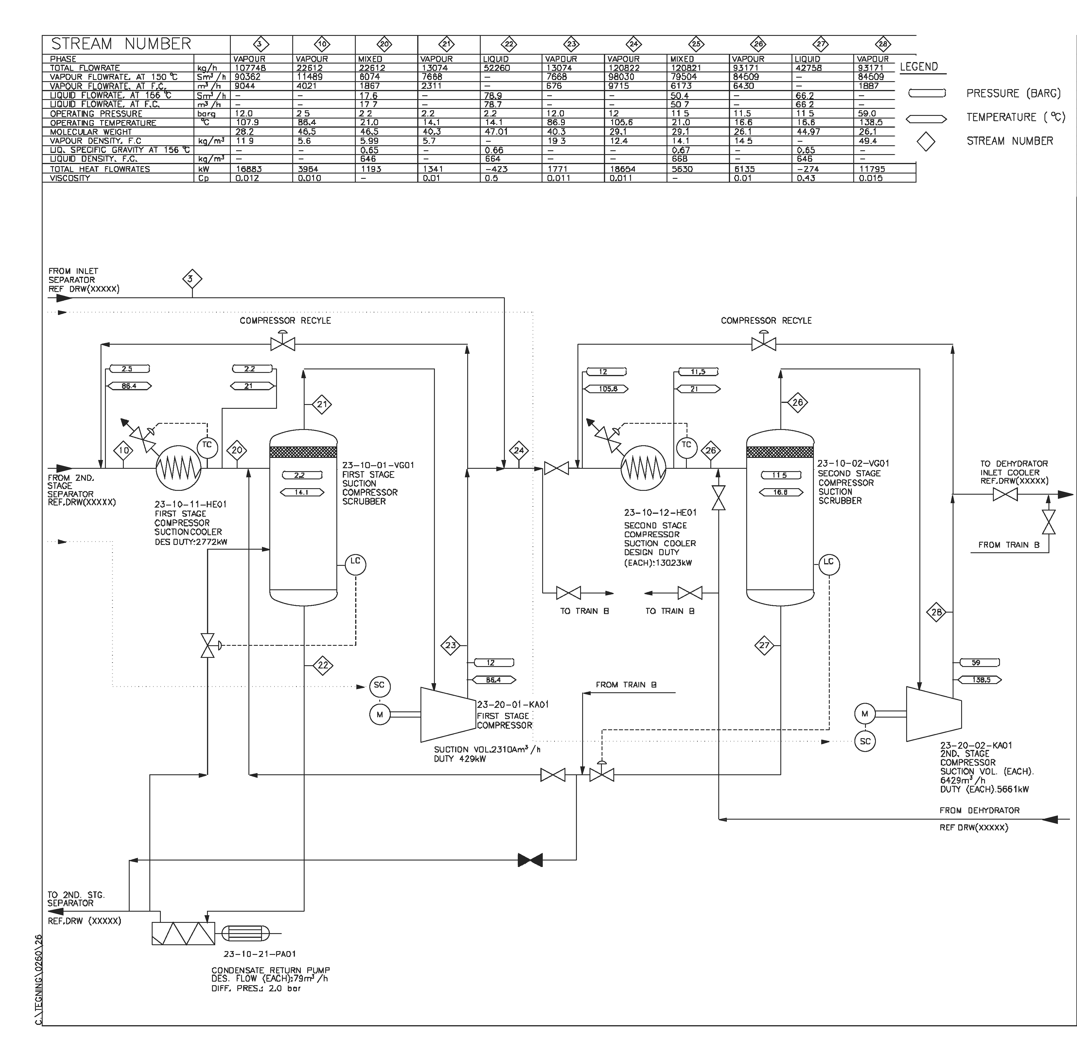
P&ids and loop diagrams are construction and documentation drawings that depict the flow of the process and illustrate the instrumentation control and measurement interactions, wiring and connections to the process. Although wiring data can be imported, the intricate nature of instrumentation usually prevents a fully automated approach, and so wiring is still performed manually to make sure it matches the intended design. This understanding possibly comes from outputs by various design automation tools such as smartplant.
All cabling and wiring has been installed, tested and labeled, recorded on the cable test report and witnessed/accepted by owner representative. Instrument loop diagrams are also called instrument loop drawings or loop sheets. 2) word description of loop functions within the title.
The hot and neutral terminals on each fixture are spliced with a pigtail to the circuit wires which then continue on to the next light. A control loop consists of transmitter/sensor, process controller, final control element. Basics of instrument loop diagrams they show all the instruments in a control loop each instrument bubble in a loop diagram represent an individual device with its own terminals for connecting wires.
Just like any other instrument, transmitters need a power supply to operate. A plot plan shows the exact location of each equipment. The loop checking checks the connection between each component in the control loop.
We talk about what they are, how th. Instrument loop diagram represents detailed drawing showing a connection from one point to control system.loop diagram shows instrument (in a symbol) and its. Also, what is loop wiring diagram?
The components within the loop have been installed in accordance with process piping, instrument air piping, mounting details and instrument drawings. Although wiring data can be imported, the intricate nature of instrumentation usually prevents a fully automated approach, and so wiring is still performed manually to make sure it matches the intended design.

Basics of Instrument Loop Diagrams Learning Instrumentation And Control Engineering
Purpose of Loop Diagrams Instrumentation Design
Instrumentation Diagrams Multiple Choice Questions and Answers
Instrumentation Diagrams Multiple Choice Questions and Answers
Instrumentation Loop Diagrams Instrumentation Tools

ICD (Instrumentation control and design) Instrumentation Engineering

Instrumentation Trouble Shooting Instrumentation
Instrumentation Loop Diagrams InstrumentationTools
Pressure Control Loop Wiring Connections Instrumentation Tools
Instrumentation Loop Diagrams InstrumentationTools
15 Loop Diagram Questions Instrumentation Tools
Field Instrumentation loop diagram
Loop Wiring Diagram Instrumentation Pdf
Instrument Loop Wiring Diagrams Wiring Library
Instrumentation Diagrams Multiple Choice Questions and Answers
Instrumentation Loop Diagrams InstrumentationTools
Loop Diagrams (Loop Sheets) Control and Instrumentation Documentation Automation Textbook
Instrument Loop Drawings

Loop Wiring Diagram Instrumentation Pdf Diagram