Intermatic T104 Timer Wiring Diagram
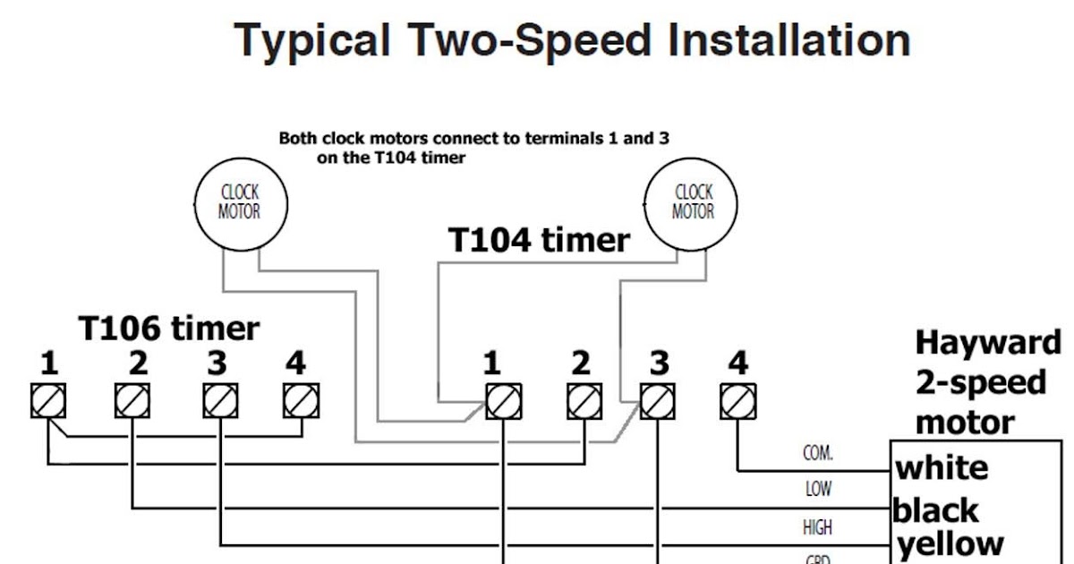
Use solid or stranded copper only wire with insulation to suit installation. Click the register link above to proceed.

Intermatic Timer T104 Wiring Diagram Download
To my pump, i have a black, red and green wire.

Intermatic t104 timer wiring diagram. T has wg v clock motor. T104 24 hour dial time switch double pole single throw (dpst) 40 amp. Use solid or stranded copper only wire.
Intermatic t 104 wiring diagram. Running pool equipment 24 hours is usually unnecessary and expensive. Outgoing, the 2 white wires are wirenutted with the white incoming line and again all tied to terminal a.
Pool pump timer wiring diagram computer wiring diagram pool wiring diagram basic. Wiring instructions:to wire switch follow diagram above. Korics is a company that dreams come true and respects your thoughts.
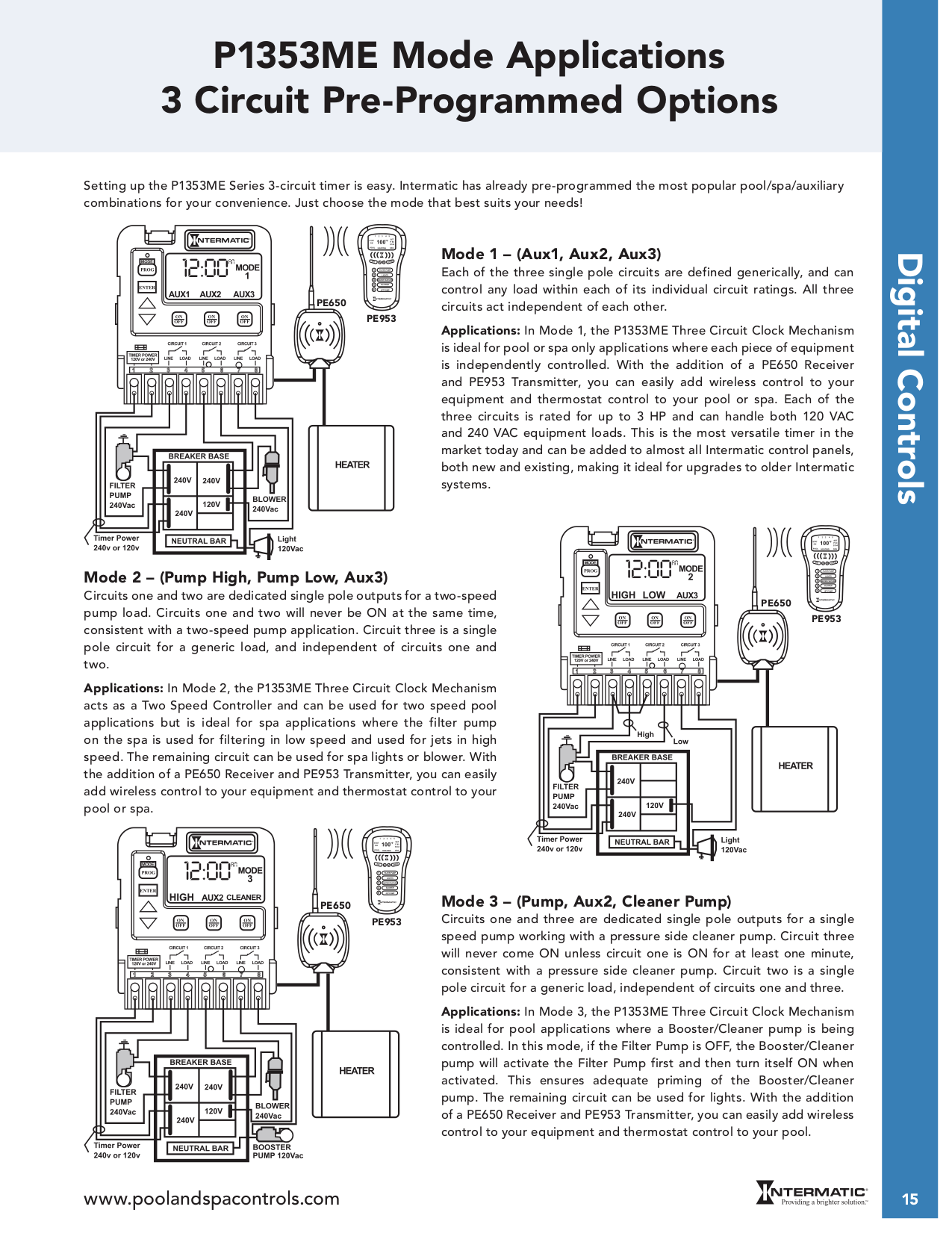
Wiring diagram 240 v 2 wire and ground clock motor: Intermatic t103 wiring diagram assortment of intermatic t103 wiring diagram. Apr 21, 2009, 01:48 pm.
T104 24 hour dial time switch double pole single throw (dpst) 40 amp. The t series mechanical time switch has proven it can stand the test of time. Assortment of intermatic timer t104 wiring diagram.
Intermatic t104 pool timer off series 40 amp 208 277 indoor 24 hour wiring pump bypass in 240v system t104r won t turn on to relay switch et1105 t104p201 programming with heater delay circuit supplementary manual pf1102t and pf1103t time control user. Following trying to remove, replace or repair the wiring in an automobile, having an accurate and detailed intermatic timer t104 wiring diagram. Intermatic timer t103 wiring diagram triing to install an intermatic t103 timer to run 3 1000w hps.
Pool pump timer bypass in 240v system intermatic wiring t104 off with heater delay circuit suraielec 7 day basic repair grasslin t104r won t turn on problem what else to do solarattic solar guidance needed for wiring of pool pump timer bypass in 240v system diy home improvement forum intermatic pool timer wiring […] Get recommended intermatic products to use when replacing another manufacturer’s product. Intermatic t basic wiring diagram, t timer volts or volts check label on side of water heater for volts & watts this timer.
The t series mechanical time switch has proven it can stand the test of time. These dependable time switches can handle electrical loads up. Lighting contactor wiring diagram with timer.
Wiring instructions:to wire switch follow diagram above. Use solid or stranded copper only wire. I bought an intermatic t103 and wire it as follows power to 1 3.
To order replacement, indicate part no. Intermatic t100 series 40 amp 24 hour outdoor mechanical timer with double pole single throw switching 240 vac gray. Note, timers vary with supply voltage.
Time pointer time dial off tripper manual lever on tripper typical wiring diagram clock motor 120/240 volt 3 wire supply to loads ground line 2 line 1 a 2 4 gr. Clock motor voltage and cycle must be as specified. You may have to register before you can post:
I have a black wire, a red wire, and a green (ground) wire. T104 24 hour dial time switch double pole single throw (dpst) 40 amp. The following steps will provide a guide on how to install the t104 timer.
A t104 timer is used for 230v supply voltage. Intermatic t104 supplementary manual manualzz. Assortment of intermatic timer t104 wiring diagram.
Use solid or stranded copper only wire. To wire switch follow diagram above. T timer requires neutral wire.
Installing an intermatic t104 timer is a great way to dramatically reduce run time and energy costs. Precision direct timer replacement series. The speaker wiring diagram and connection guide the basics you need to know speaker wire types of electrical wiring audio design.
An intermatic timer switch saves electricity when it turns a water heater off at night and when it limits the amount of time a pool s filtration system runs. It reveals the components of the circuit as streamlined forms, and also the power and also signal connections in between the tools. To my salt converter, i have a black, pink and green wire.
Assortment of intermatic timer t104 wiring diagram. To wire switch follow diagram above. These dependable time switches can handle electrical loads up to 40 a per pole and allow for up to 12 on/off operations per day.
Pool pump timer bypass in 240v system intermatic wiring t104 off diagram ground with heater delay circuit how to set a user guide i have sul181h electrical 230 volt. A wiring diagram is a simplified standard photographic depiction of an electric circuit. Intermatic t104 wiring (simple terms) i am trying to wire an intematic timer model #t104 to my pool pump.
Grässlin uk connect wiring in accordance with wiring diagram. The switch is wired to the timer. The key.jul 18, · t timer wiring diagram intermatic wall timer instructions intermatic wall timer instructions buy now model overview specifications resources digital timer with astro random and dst features 7 on.
T104 intermatic 250v time clock.

DIY water heater Pinterest
How to wire Intermatic T104 and T103 and T101 timers

SOLVED How to wire a intermatic timer T104 240 v to a Fixya


Intermatic Timer T104 Wiring Diagram Download

Get Intermatic Timer T104 Wiring Diagram Sample
SOLVED Intermatic t104p3 pool timer will turn pump Fixya

Intermatic T104 Wiring Diagram

Intermatic T104 Wiring Diagram Wiring Diagram
SOLVED How to wire a intermatic timer T104 240 v to a Fixya


Intermatic Timer T104 Wiring Diagram Download
How to wire Intermatic T12404R

How to wire Intermatic T104 and T103 and T101 timers

How to wire Intermatic T104 and T103 and T101 timers

Intermatic T104 Wiring Diagram
How to wire Intermatic T104 and T103 and T101 timers

Wiring Diagram For T104 Timer schematic and wiring diagram

Intermatic Timer T104 Wiring Diagram Download

Intermatic Timer T104 Wiring Diagram Download
Intermatic T104P201 instruction manual T104R201